Pages

click here

Tuesday, February 22, 2011

Basic Types of Drilling Machines

Basic Types of Drilling Machines
Drilling machines or drill presses are one of the most common machines found in the machine shop. A drill press is a machine that turns and advances a rotary tool into a workpiece. The drill press is used primarily for drilling holes, but when used with the proper tooling, it can be used for a number of machining operations. The most common machining operations performed on a drill press are drilling, reaming, tapping, counterboring, countersinking, and spotfacing.
There are many different types or configurations of drilling machines, but most drilling machines will fall into four broad categories: upright sensitive, upright, radial, and special purpose.
UPRIGHT SENSITIVE DRILL PRESS


Figure 1 Upright sensitive drill press
The upright sensitive drill press (Figure 1) is a light-duty type of drilling machine that normally incorporates a belt drive spindle head. This machine is generally used for moderate-to-light duty work. The upright sensitive drill press gets its name due to the fact that the machine can only be hand fed. Hand feeding the tool into the workpiece allows the operator to "feel" the cutting action of the tool. The sensitive drill press is manufactured in a floor style or a bench style.
UPRIGHT DRILL PRESSThe upright drill press (Figure 2) is a heavy duty type of drilling machine normally incorporating a geared drive spindle head. This type of drilling machine is used on large hole-producing operations that typically involve larger or heavier parts. The upright drill press allows the operator to hand feed or power feed the tool into the workpiece. The power feed mechanism automatically advances the tool into the workpiece. Some types of upright drill presses are also manufactured with automatic table-raising mechanisms.

Figure 2
  Upright drill press

RADIAL ARM DRILL PRESSThe radial arm drill press (Figure 3) is the hole-producing work horse of the machine shop. The  press is commonly refered to as a radial drill press. The radial arm drill press allows the operator to position the spindle directly over the workpiece rather than move the workpiece to the tool. The design of the radial drill press gives it a great deal of versatility, especially on parts too large to position easily. Radial drills offer power feed on the spindle, as well as an automatic mechanism to raise or lower the radial arm. The wheel head, which is located on the radial arm, can also be traversed along the arm, giving the machine added ease of use as well as versatility. Radial arm drill presses can be equipped with a trunion table or tilting tableThis gives the operator the ability to drill intersecting or angular holes in one setup.

Figure 3 Radial arm drill press


SPECIAL PURPOSE DRILL MACHINESThere are a number of types of special purpose drilling machines. The purposes of these types of drilling machines vary. Special purpose drilling machines include machines capable of drilling 20 holes at once or drilling holes as small as 0.01 of an inch.
Gang Drilling Machines


Figure 4 Gang drill press
The gang style drilling machine (Figure 4) or gang drill press has several work heads positioned over a single table. This type of drill press is used when successive operations are to be done. For instance, the first head may be used to spot drill. The second head may be used to tap drill. The third head may be used, along with a tapping head, to tap the hole. The fourth head may be used to chamfer.
Multiple Spindle Drilling Machine
The multiple spindle drilling machine is commonly refered to as a multispindle drill press. This special purpose drill press has many spindles connected to one main work head (Figure 5).All of the spindles are fed into the  workpiece at the same time. This type of drilling machine is especially useful when you have a large number of parts with many holes located close together.

Figure 5 Multispindle drill press
Micro-Drill Press
The micro drill press is an extremely accurate, high spindle speed drill press. The micro drill press is typically very small (Figure 6) and is only capable of handling very small parts. Many micro drill presses are manufactured as bench top models. They are equipped with chucks capable of holding very small drilling tools.

Figure 6 Micro drill press
Turret Type Drilling Machine
Turret drilling machines are equipped with several drilling heads mounted on a turret (Figure 6). Each turret head can be equipped with a different type of cutting tool. The turret allows the needed tool to be quickly indexed into position. Modern turret type drilling machines are computer-controlled so that the table can be quickly and accurately positioned.

Figure 6 CNC Turret type drilling machine

DRILLING MACHINES: FEATURES, FUNCTIONS AND FUTURE

DRILLING MACHINES: FEATURES, FUNCTIONS AND FUTURE

According to Riccardo Azzoni, president of Atlantic Machinery, "The greatest assets a boring machine can have are: user-friendliness, accuracy, ease of setup and affordability." Most of the other industry experts interviewed by WOOD & WOOD PRODUCTS shared similar opinions.
Peter Zurcher, national sales manager at Grass America said, "boring machines should be easy to operate with added safety features built in and easy and simple to maintain." He added that he also values straightforward changeovers in boring machines.
A.C. Brown, field service manager for Medalist Industries, added "quick, repeatable setup for a wide range of parts is an important feature of boring machines." Other priorities Brown noted include: "the capacity to bore at varying hole depths in the same setup without the use of costly fixturing; the capacity to bore mirror imaged parts within one setup; and being able to do away with U-joint type spindles and drive trains."
"Quick setups, accuracy and speed," are the most significant features noted Richard (Tim) Byrnes, president of Richard T. Byrnes Co. Gary Wells, president of Tritec Assoc., said accuracy is the greatest concern. "Precision is the overriding consideration," he said, "followed by versatility."
Roger Stiles, president of Roger Stiles & Assoc., maintained the difference between set-up time and run time is the top priority of boring machines.
Another function of a boring machine is its increased computer capabilities. "The level of computer technology applied to our machines enhances the flexibility, a key element in just-in-time production," said Walter Favruzzo, general manager at Stefani Group America. Ken Amidon, technical sales representative at Stiles Machinery, said, "The biggest thing in point-to-point machines, beside a computer, is programmable selectable spindles," which allow the operator to "put a hole anywhere." Even with a 32mm system there can be an oddball hole, he added, but an operator can put one in a hard-to-reach spot.
Multifunctionality
Some manufacturers and distributors notice a demand for versatility resulting in an increase of multi-function machines. Warren Wade, president of Tekna said that in the future "the gap between boring and true routing machines will slowly close. Point-to-point CNC boring equipment will be capable of doing more sophisticated routing procedures."
Stiles said he sees a trend in machines combining routing, boring, and edgebanding on one machine.
Machining centers: multi-function
equipment vs. dedicated machines
Some experts hold that as the boring operation becomes more computer controlled, machining centers will evolve. The boring machine is "changing rapidly into a machining center, capable of performing multi-task operations such as drilling, routing, grooving and hardware insertion," said Favruzzo. Likewise, Rolf Zollinger, machines and systems sales manager for Koch Ltd., said that more CNC adaptability will increase the machine's flexibility in the future. He added that the equipment will become "more multi-purpose, more universal, more like machining

Monday, February 21, 2011

Drill Press Work Area

Drill Press Work Area
A view of the metal-cutting area of a drill press is shown below. The workpiece is held in place by a C-clamp since cutting forces can be quite large. It is dangerous to hold a workpiece by hand during drilling since cutting forces can unpredictably get quite large and wrench the part away. Wood is often used underneath the part so that the drill bit can overshoot without damaging the table. The table also has holes for drill overshoot as well as weight reduction. A three-jaw chuck is used since three points determine a circle in two dimensions. Four-jaw chucks are rarely seen since offset of the bit is not necessary. The next section contains illustrations of drill bit chucks. To get an idea of the differing configurations of three and four-jaw chucks, please see the equivalent lathe chucks.


Drilling Characteristics

Drilling Characteristics
The characteristics of drilling that set it apart from other powered metal cutting operations are:
  • The chips must exit out of the hole created by the cutting.
  • Chip exit can cause problems when chips are large and/or continuous.
  • The drill can wander upon entrance and for deep holes.
  • For deep holes in large workpieces, coolant may need to be delivered through the drill shaft to the cutting front.
  • Of the powered metal cutting processes, drilling on a drill press is the most likely to be performed by someone who is not a machinist.

Drilling: Introduction

Drilling: Introduction
Drilling is easily the most common machining process. One estimate is that 75% of all metal-cutting material removed comes from drilling operations. 
 
Drilling involves the creation of holes that are right circular cylinders. This is accomplished most typically by using a twist drill, something most readers will have seen before. The figure below illustrates a cross section of a hole being cut by a common twist drill:


The chips must exit through the flutes to the outside of the tool. As can be seen in the figure, the cutting front is embedded within the workpiece, making cooling difficult. The cutting area can be flooded, coolant spray mist can be applied, or coolant can be delivered through the drill bit shaft. For an overview of the chip-formation process, see the Chip Formation Section.


Parting Operations


Parting Operations

Parting uses a blade-like cutting tool plunged directly into the workpiece to cut off the workpiece at a specific length. It is normally used to remove the finished end of a workpiece from the bar stock that is clamped in the chuck. Other uses include things such as cutting the head off a bolt.

Commercial Parting Tools

There is a wide variety of commercial parting tools available from tool suppliers, but most are too large to use on the 7x10. Harbor Freight sells a 5/16" parting tool (P/N 37034-0VGA, $5.99) but the top of the blade is actually about 1/16" above the center line of the 7x10.
HF_tool.jpg (20563 bytes)
This is problematic because it is important for the top of a parting tool to be right on center. Many attempts (my own included), including sanding, turning and grinding, have been described in the 7x10 interest group to remove 1/16" from the bottom of the tool holder, but few have been successful. The tool holder is pretty hard metal.
Even so, this little tool is tempting, because grinding a parting tool from a tool blank is a pain - since so much metal must be ground away - and parting tools get dull and break easily. This tool, and similar larger ones, use pre-formed cutting tools. If you break off the end, you just grind a new cutting edge and go on. I haven't done this yet, but the best solution to using the HF 5/16" parting tool may be simply to make a custom tool holder of the correct height.
Here's another 1/2" commercial parting tool. I plan to make a custom toolholder for it someday.
Parting_blade.jpg (26727 bytes)

Custom Ground Parting Tools

Grinding your own parting tool is not real difficult but it takes a long time and generates a lot of metal and grinder dust due to the relatively large amount of metal that you must remove from the blank. Here are some pictures of a typical home-ground tool. Note that the tool is tapered from top to bottom (like a narrow keystone) and from front to back to provide relief for the cutting tip. The top of the tool has been ground down by a few thousandths of an inch to align the top edge of the tool with the lathe centerline.  If you have a toolholder with adjustable tool height, this would not be necessary. Forming the parting blade near the edge of the tool allows the tool to work up close to the chuck jaws.
Parting_tool1.jpg (17601 bytes) Parting_tool2.jpg (16743 bytes) Parting_tool3.jpg (14636 bytes) Parting_tool4.jpg (14876 bytes)

Chucking the Workpiece

Parting is always done close to the chuck jaws - no more than 1/2" out, and, preferably, no more than 1/4" out. (Note: this is also relative to the diameter of the workpiece; 1/4" may be right for a 3/4" diameter workpiece, but would be too far out for a 1/8" dia. piece.) Parting cuts impose great tangential force on the workpiece that could cause the workpiece to be forced out of the chuck if you cut too far from the chuck jaws.

Adjusting the Tool Bit

For a parting cut the top of the tool should be exactly on the center line of the lathe, or no more than .005 above the center line. If the tool is a little high it will have a tendency to 'climb' the work; a little low will cause a tendency to dig in. The tip of the tool should be exactly perpendicular to the workpiece.
Parting1.jpg (24270 bytes)

Speed and Feed

Make sure the leadscrew is in the neutral position so that the leadscrew is not moving. Now lock the half nut in the engaged position to keep the carriage from moving during the parting cut. Even, better, if you have made a carriage lock, use it.
Parting cuts should be made at low speed; say 200-300 RPM or even slower.

Making the Cut

With the tip of the tool just beyond the surface of the workpiece, turn on the lathe. Slowly advance the cross-slide crank until the tool starts cutting into the metal. Keep advancing the tool until you get a steady chip curling off the workpiece and then try to maintain this cutting speed.
Parting2.jpg (36010 bytes) Parting3.jpg (29095 bytes)
It's a good idea to use cutting oil for a parting cut and you will find that the heat generated will most likely cause a fair amount of smoke as the cutting oil burns off. Avoid breathing this smoke - I haven't heard of any ill effects, but I'm sure it's not good for your lungs. A small fan to disperse it may be a good addition to your workbench.

Chatter

Parting often causes 'chatter'. If you have never heard this sound, you will easily recognize it when you first do. It is a pulsing, whining vibration that can shake the whole lathe and even cause it to move around on the workbench if is not bolted down. You can stop chatter quickly by backing off the pressure on the tool. The trick is to find the right speed at which to advance the tool with minimal chatter.
Here are some tips to minimize chatter:
  • Tool tip should be quite sharp
  • Top of tool should be right on the lathe centerline
  • Tool should be perpendicular to the workpiece
  • Gibs on cross-slide and compound should be snug
  • Saddle should be snug to the ways
  • Use carriage lock to lock saddle to ways
  • Use cutting fluid
  • Maintain steady advance of cross-slide

Finishing the Parting Cut

Keep advancing the tool until it reaches the center of the workpiece. As you get close, the workpiece is suspendend by a thin stalk of metal.
Parting4.jpg (37528 bytes)
Be careful: if the workpiece extends from the chuck more than a few times its diameter, the end of the workpiece can start to swing in a dangerous arc. As you get near the center, you may need to slow down the chuck speed to keep things safe. If you notice the workpiece starting to wobble, stop the lathe and move the workpiece back and forth by hand to break it free.
The end of the workpiece that you cut off will generally have a pretty rough finish and a little stalk of metal protruding from the end.
Parting5.jpg (29782 bytes)
One limitation of parting tools is the diameter of the work that can be parted. The tool illustrated here is a little under 3/8" long and can part off work up to 3/4" in diameter. In the previous picture you can see that the edge of the work is rounded because it was rubbing up against the shoulder of the cutting tool. If you make the tip of the tool much longer than about 1/2" it starts to get too limber and will easily break off. So on a small lathe like this, the largest diameter work that you can part off is probably around 1".  To cut off bigger work, you can use a small hacksaw while turning the work at low speed in the lathe.  Even better, if you have a metal-cutting  bandsaw, use it to cut off the work.  I nearly always use the bandsaw for work larger than 1/2" diameter.
The final step it to mount this piece in the chuck and make a facing cut to clean up the end. One problem with this step is that the chuck jaws can mar the finished workpiece. If you look carefully at the next picture you can actually see the imprint of the chuck jaws. To avoid this, you could wrap the workpiece in a thin strip of emory paper, or similar protective material, before clamping it.
Parting6.jpg (25609 bytes)

Filing and Polishing on the Lathe

Filing and Polishing on the Lathe


Filing and polishing are performed on the lathe to remove tool marks, reduce the dimension slightly, or improve the finish.


Filing on the Lathe

      Mill files are generally considered best for lathe filing. The bastard cut mill type hand file is used for roughing and the second cut mill-type hand file for the finer class of work. Other types such as the round, half-round, and flat hand files may also be used for finishing irregular shaped workplaces. Never use a file without a handle.

     For filing ferrous metals, the lathe spindle speed should be four or five times greater than the rough turning speed. For filing nonferrous metals, the lathe spindle speed should be only two or three times greater than the roughing speed. Too slow a speed may cause the workpiece to be filed out of round, while too high a speed will cause the file to slide over the workpiece, dulling the file and glazing the piece.

NOTE: When filing, file left-handed if at all possible to avoid placing your arm over the revolving chuck or lathe dog.

      The file is held at an angle of about 10° to the right and moved with a slow sliding motion from left to right so that the teeth will have a shearing action (Figure 3-100).The direction of stroke and angle should never be the opposite, as this will cause chatter marks on the piece. The file should be passed slowly over the workpiece so that the piece will have made several revolutions before the stroke is completed. The pressure exerted on the file with the hands should be less than when filing at the bench. Since there are less teeth in contact with the workpiece, the file must be cleaned frequently to avoid scratching.


Figure 3-100. Filing on the lathe.


      Since filing should be used for little more than to remove tool marks from the workpiece, only 0.002 to 0.005 inch should be left for the tiling operation.


Polishing on the Lathe

      Polishing with either abrasive cloth or abrasive paper is desirable to improve the surface finish after filing. Emery abrasive cloth is best for ferrous metals while abrasive paper often gives better results on nonferrous materials. The most effective speed for polishing with ordinary abrasives is approximately 5,000 feet per minute. Since most lathes are not capable of a speed this great for an average size workpiece, it is necessary to select as high a speed as conditions will permit.


Figure 3-101. Polishing on the lathe.


      In most cases the abrasive cloth or paper is held directly in the hand and applied to the workpiece, although it may be tacked over a piece of wood and used in the same manner as a file. Improvised clamps may also be used to polish plain round work.

      Since polishing will slightly reduce the dimensions of the workpiece, 0.00025 to 0.0005 inch should be allowed for this operation. Figure 3-101 shows how to hold the abrasive strip when polishing. Note that the ends of the strip are separated. This prevents the strip from grabbing and winding around the work, which could pull the operator's hand into the work. Move the polishing strip slowly back and forth to prevent material building up on the strip which causes polishing rings to form on the work. To produce a bright surface, polish the work dry. To produce a dull satin finish, apply oil as the polishing operation is in progress.

Recessing Tools For The Engine Lathe


Recessing Tools For The Engine Lathe

The upper illustration in Fig. 1 shows a bushing A which is held by the outside in regular chuck jaws. This work is to be done on the engine lathe, and the recess is to be cut at the same setting. A forged tool B is held in the regular tool-post G on the cross-slide of the lathe, and is forced into the required depth by hand. After this the longitudinal feed is started and the remainder of the recess cut. This type of tool is much used for lathe work when only one or two pieces are to be machined. Its advantages are that it can be easily made and quickly adjusted. Its disadvantage is that it has a tendency to chatter, and is, therefore, suitable only for very light cutting.
Fig. 1. Two Simple Types of Recessing Tools for the Engine Lathe
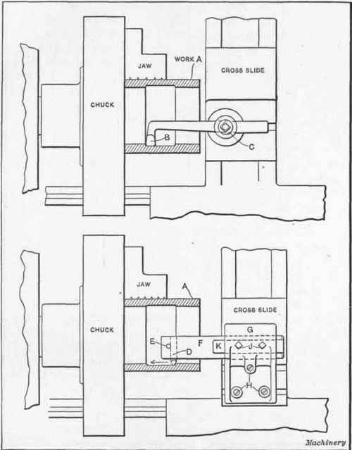
Fig. 1. Two Simple Types of Recessing Tools for the Engine Lathe.
The device shown in the lower portion of the same illustration is much more rigid, but is not nearly as adaptable to various conditions. In this arrangement the tool D is of round section and is held in place by taper pin E. The bar F is of steel and is secured in the holder G by the two screws J which bear against a flat K on the bar. Three screws H enter shoes in the cross slide T-slots and secure the holder firmly to the slide.

Bar For Undercutting, Facing And Boring In The Vertical Turret Lathe


Bar For Undercutting, Facing And Boring In The Vertical Turret Lathe

A very difficult condition for which to design tools is shown in Fig. 6, as the work itself requires rapidity of handling and is a steel casting weighing about 300 pounds. Only a part of the piece is shown at A, but it will readily be seen that it is necessary to make the bar in such a way that the tools can be used to do all the cutting indicated by the arrows; i. e., undercut the upper flange, double-bore the interior, and face the lower shoulder. As the fixture on which the work was held was of the indexing variety and was very much off center, it was not expedient to run at high speed. Therefore, the double boring was of assistance in increasing the production. It will be noted that the hole through which the tools pass is of small diameter, which makes the problem still more difficult. The shank of the bar B fits the turret hole at its upper end and is slotted so that the pin F in the turret will act as a driver. (This feature is patented by the Bullard Machine Tool Co.) The lower part of the bar is eccentric to the shank in order to obtain the necessary clearance when the tools are in action. Even the tools themselves are considerably out of the ordinary in that they will cut in two directions. The upper tool D is used for undercutting the flange and also for boring, while the lower tool E is used for facing the lower shoulder and partially boring the interior. Both these tools have backing-up screws G and are held in place by the headless set-screws.
Fig. 6. Bar for Undercutting:, Facing and Boring in the Vertical Turret Lathe and Gage used in setting ToolsFig. 6. Bar for Undercutting:, Facing and Boring in the Vertical Turret Lathe and Gage used in setting Tools.
As it was necessary to set these two tools so that they would cut approximately the same diameter, the gage shown at the right of the figure was made to assist in the setting. The V-block K was slotted to receive the steel strip J so that distance L would measure the correct distance from the bar shown in section at M. It is obvious that the gage could be placed against the bar so that tools could be set out the right amount by means of the backing-up screws. This bar gave fairly satisfactory results although some trouble was experienced with chips, as there was considerable stock to remove. There was likewise a slight tendency to chatter when using a heavy feed, but this was remedied by careful grinding to make the cut as easy as possible. It must be remembered that the conditions were about as awkward as they could be, and the lack of room made it necessary to cut down the bar to such an extent that it was hardly heavy enough for the work. Taken as a whole, however, the action was satisfactory for a roughing tool. It was not used for finishing cuts.

Tapping and metalworking engineering taps


Tapping and metalworking engineering taps

Mini-lathes are very good at cutting threads. Using the ability of the lathe spindle to drive the leadscrew we can keep cutting many different internal and external threads so long as we think of new ways to arrange the change gears. However, what happens when we want an internal thread in a job to take an M5 bolt? The threading capacity of the lathe will not be much good to us here, unless we have a very very small internal threading tool and a very large amount of time on our hands.
For small holes, up to about a diameter of 16mm, it is advisable to make an internal thread using a metalworking tap. A tap is a internal threading tool made from a peice of hardened steel specifically for making screw threads.
There are supposed to be three types of tap:
  • Bottoming Tap - has a cutting edge right to the end for making a thread to the bottom of a blind hole.
  • Plug Tap - sort of half way... most commonly used tap
  • Taper Tap - has a long taper and is commonly used when the material being tapped is tough to work with.
When starting with a lump of metal, we do not use the tap to make the entire hole, and the thread. No. We first use a standard drill to make a hole, and then use to tap to thread that hole. What size should the initial hole be? The table below shows the common sizes - it is often useful to keep a stock of drill bits with the taps - to avoid wasting time trying to find the correct drill bit and matching tap. It is also possible to buy sets of drills and taps of the correct sizes. A 2mm drill bit does not have a great life expectancy, so buy several drill
Here is a selection of the drill sizes that go with common tap sizes.
ScrewDrill size
M21.60
M2.52.05
M32.50
M3.52.90
M43.30
M4.53.70
M54.20
M65.00
M76.00
M86.80
M97.80
M108.50
M1210.20
M1412.00


Tapping by hand

If you are "tapping a hole" ie using a tap to cut a thread into a drilled hole by hand, it is normal to hold the tap in a tap wrench. These are available virtually for free on places like ebay. You twist the tap into the hole, and, every couple of turns in, you make a half-turn backwards. This helps break up the chips that the tap cutting edge are making.
It is important to use a cutting fluid with the taps. When cutting aluminium, use kerosense or WD40. When cutting steel use some oil.
It is very easy, especially with thinner taps, to break the tap. If the tap snaps off in your hole, then you are in trouble. Always make sure sure keep the tap properly lined up with the hole being tapped. This is difficult to do by hand.

Tapping by micro mill

This process is not normally recommended in the text books, but I find it works well in holes up to about M6, after which, the micro mill runs out of power. It is possible to use the rotational action of the micro mill to turn the tap and tap the hole. Of course, the tap must be drawn into the hole as the thread is cut, so you must be careful.
My procedure is roughly as follows:loosen the clamp bolt on the quill of the micro mill before tapping
  • Loosen off the quill clamp bolt on the micro mill as shown right. This allows the quill to move easy.
  • Disengage the quill feed so that the vertical action of the micro mill is controlle by the large handle (what I call "drill press mode")
  • Using a drill chuck in the micro mill, first drill the correct sized hole in the part as shown in the table above.
  • Then use the vertical leadscrew at the back of the micro-mill to raise the chuck up
  • Remove the drill and replace with the tap
  • Lower the tap down until it touches to work, with the large quill handle wound fully up.
  • Give the hole tap and hole a generous squirt of kerosene.
  • Set the mill to forwards direction.
  • Place on hand on the speed control and one hand on the quill "drill press" handle.
  • "click" the power into the on position.. the mill will not move at this point.
  • Put some force down on the drill press handle - perhaps the weight of your forearm.
  • Slowly increase the power until the tap starts to turn..
  • Keep it steady until the tapping reaches as far as you want
  • Then reserve the process to bring the tap out - lifting the drill press handle to raise the tap out as it unscrews.
  • You might have to do this in stages to get the chips out of the hole, especially if it is a blind hole.
  • This does not give a particularly perfect tapped hole, but it is usually good enough, and much faster than doing it by hand.